Orifice Plate Beta Ratio Explained and Why It Matters
In differential pressure flow measurement, orifice plate beta ratio explained simply means understanding the relationship between the orifice bore diameter and the internal diameter of the pipe. That ratio affects differential pressure generation, permanent pressure loss, signal strength, flow range, and measurement uncertainty. For buyers and engineers working with Flowell components, beta ratio is one of the key details that connects the orifice plate, holder, flange assembly, and field installation.
The beta ratio is not just a calculation on a sizing sheet. It helps determine whether an orifice plate will create a strong enough pressure differential without creating unnecessary restriction in the process line. It also influences how the plate works with surrounding hardware such as RTJ plate holders, universal orifice plates, and complete orifice plate flow meter systems.

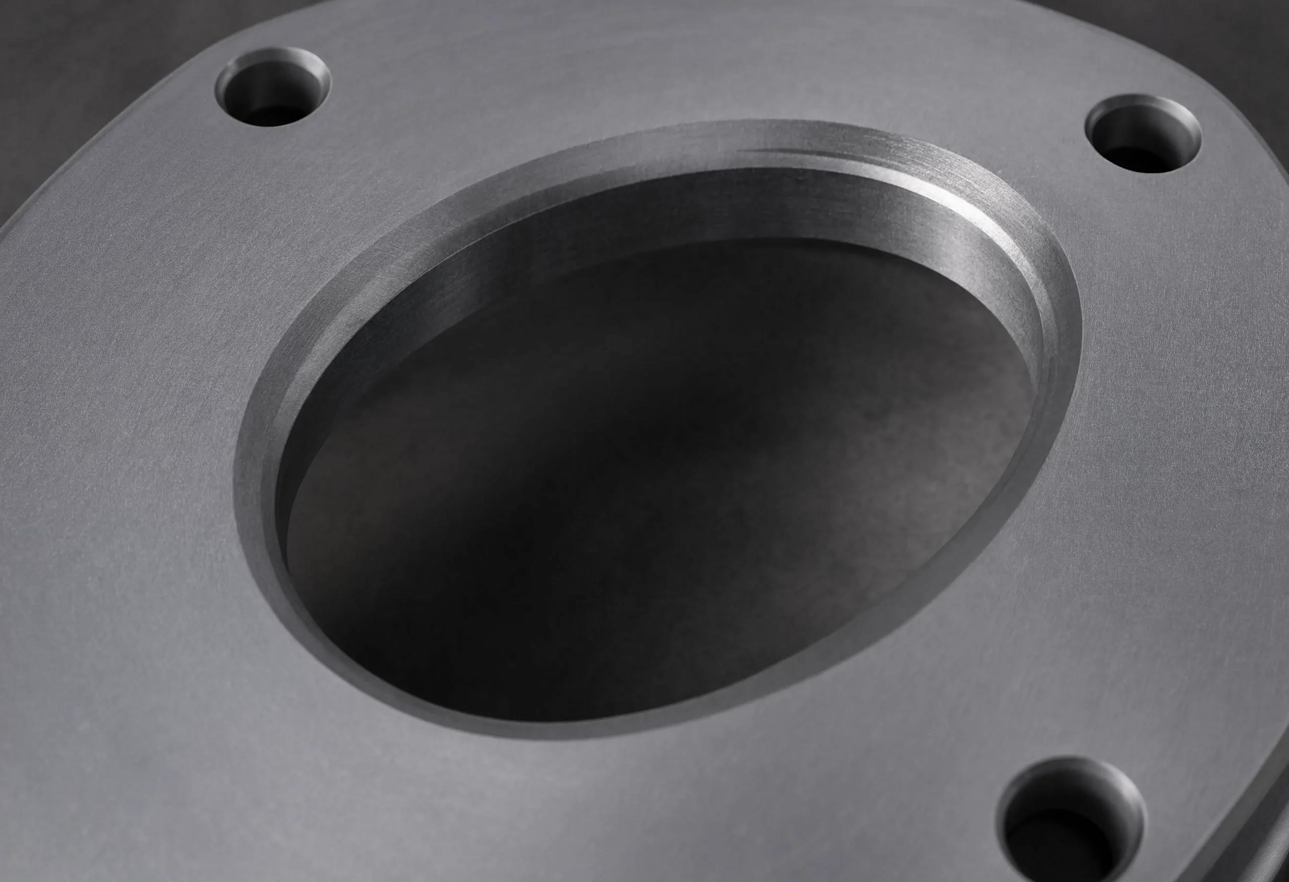
Orifice plate beta ratio explained
The beta ratio is calculated by dividing the orifice bore diameter by the internal diameter of the pipe. In formula form, it is beta ratio = d / D. The letter d represents the orifice bore diameter, and the letter D represents the pipe internal diameter. The result is a dimensionless value that shows how large the bore opening is compared with the pipe that carries the fluid.
A lower beta ratio means the orifice opening is smaller relative to the pipe. A higher beta ratio means the opening is larger relative to the pipe. That simple relationship has a major effect on how the measurement assembly behaves once fluid moves through the line. As flow passes through the restriction, velocity increases and static pressure drops. The pressure difference across the plate is then used to calculate flow.
Beta ratio selection should never be based on nominal pipe size alone. Actual internal diameter, operating flow range, media properties, pressure, temperature, and allowable pressure loss all matter.
Orifice plate beta ratio explained for engineers
For engineers, the beta ratio is a performance variable. It influences discharge coefficient, differential pressure range, permanent pressure loss, Reynolds number behavior, installation sensitivity, and usable operating range. A plate with a poorly matched beta ratio can create unstable readings even when the plate material and line size appear correct.
Lower beta ratio
A lower beta ratio usually creates a stronger differential pressure signal because the bore is smaller relative to the pipe. That can help low-flow sensitivity, but it can also increase permanent pressure loss.
Higher beta ratio
A higher beta ratio usually creates less restriction and lower pressure loss. The tradeoff is a weaker differential pressure signal, which can reduce sensitivity at the low end of the operating range.
Mid-range balance
Many practical designs aim for a balance between signal strength, process efficiency, transmitter range, and standards-based predictability.
How beta ratio affects differential pressure flow measurement
Orifice plate measurement depends on a predictable restriction in the pipe. When the beta ratio changes, the behavior of that restriction changes. A tighter restriction increases velocity through the bore and produces a stronger differential pressure signal. A larger bore reduces the restriction and typically lowers permanent pressure loss, but the signal may become weaker.
This matters because the transmitter needs a usable differential pressure signal across the expected flow range. If the signal is too low, small changes in flow may be harder to detect. If the restriction is too severe, the process may experience pressure loss that creates operational cost or performance concerns. The best beta ratio is the one that fits the process conditions, not the one that looks convenient on a generic chart.
| Beta Ratio Direction | Measurement Effect | Potential Tradeoff |
|---|---|---|
| Lower beta ratio | Stronger differential pressure signal and better low-flow sensitivity | Higher permanent pressure loss and greater process restriction |
| Higher beta ratio | Lower pressure loss and less restriction in the line | Weaker differential pressure signal and possible low-flow sensitivity issues |
| Balanced beta ratio | Better fit between transmitter range, process needs, and expected flow | Requires accurate operating data and sizing review |
Pressure drop and signal strength considerations
Signal strength and pressure loss are tied together. A beta ratio that creates a strong signal may not be acceptable if the pressure loss is too high for the process. A beta ratio that preserves pressure may not work if the transmitter cannot measure low-flow conditions reliably. This is why Flowell recommends reviewing beta ratio together with line size, process data, transmitter range, installation geometry, and surrounding hardware.
Beta ratio, RTJ plate holders, and assembly fit-up
Beta ratio is a bore relationship, but the plate still has to be held correctly in the assembly. In ring joint flange applications, RTJ plate holders help position the orifice plate within the ring joint orifice flange arrangement. That makes holder selection part of the broader measurement conversation, especially when a replacement holder, replacement plate, or updated bore requirement is involved.
When a process changes, the original plate bore may no longer fit the actual operating range. If the bore changes, the holder style and fit-up details may also need to be reviewed. Flowell’s RTJ plate holder specifications explain the difference between Style 560 integral holders and Style 590 replaceable plate holders, which can matter when maintenance or future bore changes are expected.
Holder alignment
The holder must support proper plate positioning so the bore sits correctly in the flow path. Poor alignment can introduce uncertainty that sizing calculations alone cannot fix.
Flange compatibility
Ring size, flange type, pressure class, and seating surfaces should be confirmed before a replacement holder or plate is ordered.

Service conditions
Pressure, temperature, media, corrosion exposure, and field environment affect whether the holder, plate, and material selection make sense for the application.
Selecting the correct beta ratio for your application
Choosing the correct beta ratio requires more than picking a middle value. The right selection depends on what the application demands from the meter and what the process can tolerate. The goal is to produce a measurable, stable differential pressure signal without creating unnecessary pressure loss or moving outside recognized measurement limits.
A successful selection process starts with accurate operating data. Engineers typically evaluate candidate bore sizes and compare differential pressure output across minimum, normal, and maximum flow conditions. They also review fluid properties, pipe dimensions, transmitter range, Reynolds number, and available straight run. The selected beta ratio should support the measurement goal across the full operating range, not just at one flow point.
Process inputs for beta ratio selection
- Line size and actual pipe inside diameter
- Fluid type, density, viscosity, and composition
- Minimum, normal, and maximum flow rates
- Operating pressure and temperature
- Allowable permanent pressure loss
- Required measurement accuracy
Assembly inputs that should be reviewed
- Orifice plate style and material
- Holder type and fit-up requirements
- Flange arrangement and pressure class
- Meter tube or straight-run conditions
- Transmitter span and resolution
- Known upstream disturbances or flow profile issues
For users who already have operating data ready, Flowell sizing support is the most direct next step. If you need product help before sizing, contact Flowell with your line data, service conditions, and replacement details.
Recommended beta ratio ranges and standards
Industry standards matter because orifice plate calculations rely on validated assumptions about geometry, flow conditions, and installation requirements. Standards such as ISO 5167 are commonly referenced for differential pressure flow measurement using pressure differential devices. These references help define the conditions where equations, coefficients, and installation practices are expected to produce predictable results.
Many standard concentric sharp-edged orifice plate applications fall within a beta ratio range around 0.10 to 0.75, with many practical selections often landing between 0.20 and 0.70. The final acceptable range depends on the standard being applied, plate type, tapping arrangement, Reynolds number, pipe condition, and installation details.
| Range Area | What It Usually Means | Review Priority |
|---|---|---|
| Low beta ratio | Small bore relative to pipe inside diameter | Check pressure loss, process restriction, and transmitter range |
| Mid-range beta ratio | Often a practical balance of signal strength and pressure loss | Confirm actual process data and installation requirements |
| High beta ratio | Large bore relative to pipe inside diameter | Check low-flow signal strength, uncertainty, and standards limits |
Why beta ratio standards matter
Working within recommended ranges helps maintain predictable discharge coefficients, lowers the risk of unusual flow behavior, and supports more dependable uncertainty expectations. Operating outside the conditions assumed by the standard can increase the risk of inaccurate, unstable, or hard-to-explain measurement results.
Common beta ratio mistakes that cause measurement problems
Many measurement problems begin before the plate is installed. A beta ratio can be wrong because the pipe inside diameter was assumed, the operating flow range changed, the transmitter was not considered, the pressure loss was ignored, or the replacement plate was copied from an old setup that no longer reflects the process.
Design and sizing mistakes
- Using nominal pipe size instead of actual internal diameter
- Sizing from only one flow point
- Ignoring minimum and maximum flow conditions
- Overlooking transmitter range and resolution
- Failing to review permanent pressure loss
- Assuming the old bore is still correct after process changes
Installation and hardware mistakes
- Ignoring upstream flow disturbances
- Using a worn or damaged plate
- Ordering a holder without confirming ring size
- Reusing hardware with damaged seating surfaces
- Overlooking alignment and fit-up concerns
- Replacing the plate without reviewing the full measurement assembly
These issues are closely tied to broader accuracy factors. Flowell’s article on flow measurement uncertainty explains how process data, installation geometry, component condition, and instrument limits can all affect confidence in the final reading.
How plate condition affects beta ratio performance
The beta ratio calculation assumes the bore geometry is known and the plate is in acceptable condition. In the field, wear can change that assumption. Erosion, edge rounding, corrosion, nicks, deposits, or mechanical damage can affect how the restriction behaves. Even small changes at the bore edge can influence discharge behavior and increase uncertainty.
This is especially important in applications where the orifice plate has been in service for a long time or where media conditions are abrasive, dirty, corrosive, or prone to deposits. If a plate is damaged, the original beta ratio may no longer describe how the plate behaves in practice. The same issue applies when a plate has been handled poorly during inspection or replacement.
When plate condition is questionable, replacing or reworking the plate may be smarter than trying to troubleshoot around unstable data. Flowell’s guide to orifice plate edge wear and measurement accuracy covers this issue in more detail.
Beta ratio in oil, gas, and industrial flow applications
Beta ratio selection is especially important in oil, gas, petrochemical, power, water, steam, and broader industrial service because flow measurement often supports production decisions, process control, allocation, performance tracking, and maintenance planning. Poor sizing can lead to weak signals, excess pressure loss, drift, low-flow instability, or repeated field troubleshooting.
Oil and gas measurement
Production, processing, and pipeline applications often require durable assemblies that can handle demanding field conditions while maintaining repeatable measurement behavior.
Steam and utility service
Steam applications require careful attention to temperature, pressure, condensate behavior, and instrumentation setup so the selected beta ratio supports stable readings.
Industrial process lines
Chemical, water, and plant process lines may involve corrosion, solids, changing flow rates, or pressure constraints that affect plate and holder decisions.
Users comparing available product options can browse Flowell’s flow measurement products, review broader flow measurement systems, or compare related devices such as venturi flow meter systems.
Beta ratio selection checklist
A strong beta ratio selection process brings sizing, hardware, installation, and maintenance details together. Before ordering or replacing a plate, the following checklist can help reduce avoidable problems.
| Review Area | Questions to Confirm | Why It Matters |
|---|---|---|
| Pipe data | Do you know the actual inside diameter, schedule, and line size? | Beta ratio depends on real internal diameter, not nominal size alone |
| Flow range | Are minimum, normal, and maximum flow rates known? | The selected bore must work across the full operating range |
| Pressure loss | How much permanent pressure loss can the process tolerate? | Too much restriction can create process and energy penalties |
| Transmitter fit | Will the transmitter read the expected differential pressure reliably? | Signal strength must be usable at low and high flow conditions |
| Assembly fit | Does the plate match the holder, flange, and installation hardware? | Poor fit-up can increase measurement uncertainty |
| Condition review | Is the plate edge clean, sharp, and free from wear or damage? | Damaged bore geometry can change measurement behavior |
Orifice Plate Beta Ratio FAQs
What is the beta ratio in an orifice plate?
The beta ratio is the ratio of the orifice bore diameter to the internal diameter of the pipe. It shows how large the plate opening is compared with the pipe carrying the fluid.
Why is orifice plate beta ratio important?
Beta ratio affects differential pressure signal strength, permanent pressure loss, measurement sensitivity, and uncertainty. A poorly selected beta ratio can create unstable readings or unnecessary process restriction.
Does a lower beta ratio create more differential pressure?
Yes. A lower beta ratio usually creates a stronger differential pressure signal because the bore opening is smaller relative to the pipe diameter. The tradeoff is usually higher permanent pressure loss.
Is a higher beta ratio always better?
No. A higher beta ratio may reduce pressure loss, but it can also create a weaker differential pressure signal, especially at low flow rates.
How does beta ratio relate to RTJ plate holders?
Beta ratio defines the relationship between plate bore and pipe inside diameter, while RTJ plate holders help position the orifice plate in ring joint flange assemblies. When the bore or plate changes, holder fit-up and compatibility should also be reviewed.
What information is needed to choose the correct beta ratio?
Useful information includes line size, actual internal diameter, fluid type, pressure, temperature, density, viscosity, flow range, allowable pressure loss, transmitter range, and installation details.
Get help with orifice plate sizing and flow measurement components
If you need help with beta ratio, bore sizing, replacement plates, RTJ holder fit-up, or complete orifice plate assemblies, Flowell can review the details that matter. Start with sizing support, send project details through contact Flowell, or return to the Flowell homepage to review additional flow measurement products.