Flow Conditioning Requirements for DP Flow Meters: Straight Run and Installation Guide
Getting accurate readings from a differential pressure meter starts long before the fluid reaches the primary element, which is why flow conditioning requirements for DP flow meters deserve attention at the design stage. Differential pressure, or DP, meters are trusted across oil and gas, refining, chemical processing, power generation, and water treatment because they are durable, proven, and adaptable. Their accuracy, however, depends on the velocity profile entering the meter. Elbows, valves, reducers, tees, pumps, and strainers all distort that profile, and a distorted profile produces a pressure signal that no longer matches the real flow rate.
A DP meter works by creating a restriction in the pipe and measuring the pressure drop across it. Higher flow creates a larger pressure drop. Orifice plates, venturi tubes, flow nozzles, cone meters, wedge meters, and averaging pitot tubes all follow this principle, and each assumes the fluid arrives in a stable, predictable condition. When swirl, asymmetry, or pulsation reaches the meter, the result can be biased readings, noisy signals, and poor repeatability. The sections below explain how straight pipe, conditioning devices, and good installation practice work together to protect measurement quality.
Why Velocity Profile Controls DP Measurement Accuracy
Every DP flow equation assumes a known relationship between velocity and pressure drop. That relationship holds when the flow is fully developed, symmetrical around the pipe centerline, and free of rotation. Real piping rarely delivers those conditions on its own. A single elbow pushes the fastest part of the flow toward one side of the pipe. Two elbows in different planes can spin the fluid into swirl. A throttled control valve can throw a high-energy jet down the line.
Because differential pressure flow measurement infers flow rate from geometry rather than counting volume directly, the meter cannot tell the difference between a pressure drop caused by flow and one caused by a disturbed profile. That is the core reason conditioning matters. It makes field conditions match the assumptions used when the meter was designed, calibrated, or specified.
Flow Conditioning Requirements for DP Flow Meters: Straight Run and Conditioner Basics
Requirements vary with meter type, pipe size, fluid properties, accuracy goals, and the upstream piping layout. The aim is always the same: let the fluid approach the meter in a repeatable, measurable state by minimizing swirl, reducing profile distortion, and giving turbulence time to settle.
The main factors that shape the requirements include:
- The type and location of upstream fittings and valves
- The pipe diameters of straight run available before and after the meter
- The beta ratio, which is the bore diameter divided by the pipe diameter
- Whether the fluid is gas, liquid, steam, or multiphase
- The Reynolds number and expected flow range
- The measurement purpose, such as custody transfer, allocation, control, or monitoring
- The manufacturer recommendations and the standard that governs the installation
Published guidelines give minimum values, but they are a starting point rather than a substitute for application review. A basic monitoring line can tolerate more uncertainty than a custody transfer meter. A compact skid often needs more aggressive conditioning than a long pipeline with generous straight run.
How Flow Conditioning Requirements for DP Flow Meters Change by Meter Type
Different primary elements react differently to disturbed flow. The table below summarizes the general sensitivity of common DP elements so designers know where to look first.
| Primary element | Sensitivity to upstream disturbance | Conditioning consideration |
|---|---|---|
| Orifice plates | High, especially at larger beta ratios | Long straight run or a conditioner is commonly needed after bends and valves |
| Venturi tubes | Lower than orifice plates | Shorter straight run is often acceptable, but swirl still needs control |
| Flow nozzles | Moderate | Follow the standard and manufacturer guidance for the bore ratio |
| Cone and wedge meters | Lower, thanks to built-in profile handling | Verify the supplier recommendations for each installation |
| Averaging pitot tubes | Moderate to high | Straightening vanes can reduce the required run |
For a closer look at how a complete metering package is assembled around the plate, see these orifice plate flow meter systems, where the plate, holder, taps, and meter tube are specified together.
Upstream and Downstream Straight Run Guidelines
Straight pipe is the oldest and simplest way to improve DP accuracy. Straight run is measured in pipe diameters, written as D. A 10D requirement on a 6-inch pipe means roughly 60 inches of straight pipe between the disturbance and the meter. The more severe the disturbance, the more run is typically needed, and larger beta ratios demand more of it because the meter is more sensitive to profile distortion.
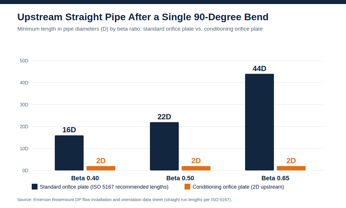
The chart below compares recommended upstream lengths after a single 90-degree bend for a standard orifice plate and for a conditioning orifice plate. Values follow ISO 5167 as published in the manufacturer data sheet.
| Beta ratio | Standard orifice plate (ISO 5167) | Conditioning orifice plate |
|---|---|---|
| 0.40 | 16D | 2D |
| 0.50 | 22D | 2D |
| 0.65 | 44D | 2D |
At a beta ratio of 0.40, moving from 16D to 2D is a reduction of about 88 percent in required upstream pipe. Those diameters turn into real length quickly, as the next chart shows for common line sizes.
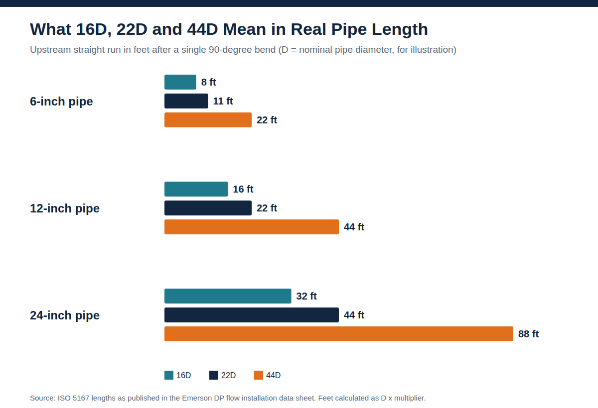
Downstream straight pipe matters too. Pressure recovery and downstream flow behavior can influence some primary elements, so downstream requirements should be respected even though they are usually much shorter than upstream ones. Poor downstream piping can create recirculation zones or unstable pressure recovery that affects the DP signal.
Orifice metering practice in natural gas is governed by API MPMS Chapter 14.3.2, which sets design and installation parameters for concentric, square-edged orifice meters and warns that measurement bias can result from inadequate flow conditioning or too little upstream pipe. Older practice commonly paired 17 diameters of meter tube with a tube bundle placed seven diameters upstream, so always confirm which edition your contract or procedure references.
Common Sources of Flow Disturbance in DP Installations
Disturbance is one of the leading causes of unstable DP readings. Space limits, equipment placement, and maintenance access often put fittings and valves close to the meter, so ideal conditions are the exception. Typical culprits include:
- Single elbows located too close to the meter
- Multiple elbows in the same plane or in different planes
- Control valves and partially closed isolation valves upstream
- Tees, headers, and branch connections
- Reducers, expanders, and sudden changes in pipe diameter
- Pumps, compressors, and blowers
- Strainers, filters, separators, and heat exchangers
- Gaskets protruding into the bore, misaligned flanges, or rough weld beads
- Short-radius bends and fabricated spool pieces
Each one affects the profile differently. A single elbow creates an asymmetric profile. Two elbows in different planes create swirl. Throttled valves produce jets, and reducers can cause separation and recirculation. Swirl is especially harmful because it breaks the relationship between velocity and differential pressure, leading to over-reading, under-reading, and noisy signals.
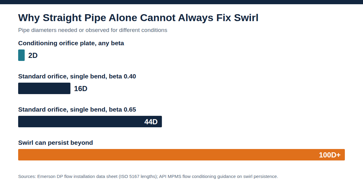
Swirl is also slow to fade. API guidance written for turbine meters notes that swirl can persist beyond 100 pipe diameters of straight pipe, which is far more than most piping layouts can provide.
Pulsation and Installation Details That Distort the DP Signal
Pulsating flow from reciprocating compressors, pumps, or unstable control loops adds another problem. Transmitter damping can make the output look smooth, but it does not remove the underlying bias. Significant pulsation may call for different meter selection, pulsation dampening, or a revised piping layout.
Small installation details matter as well. A gasket that protrudes into the bore, a misaligned flange, or debris caught upstream of a plate can disturb the flow enough to shift the reading. Installation quality is therefore part of conditioning, not a separate topic.
How Conditioning Improves Measurement Stability
When the velocity profile is stable, the differential pressure signal becomes more consistent and more representative of actual flow. A well-conditioned installation improves:
- Accuracy of the calculated flow rate
- Repeatability across operating conditions
- Signal stability at the DP transmitter
- Reliability of custody transfer and allocation data
- Control loop performance
- Troubleshooting efficiency and long-term meter performance
Operators see fewer erratic readings, engineers gain confidence in the data, and maintenance teams stop chasing false instrument faults. A uniform profile can also reduce vibration and pressure fluctuation in some systems, which supports broader reliability.
Flow Straighteners, Conditioning Plates, and Vanes Compared
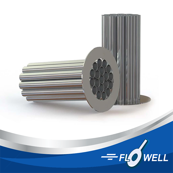
When straight run alone is impractical, a conditioning device is installed upstream to reduce swirl and redistribute the velocity profile. Straightening vanes guide the flow into a more axial direction and are often used near bends, while tube bundles divide the flow into smaller passages and perforated plates reshape the profile in a short distance.
| Device | Strength | Trade-off |
|---|---|---|
| Straightening vanes | Reduce swirl effectively in compact runs | Must be designed and installed correctly |
| Tube bundles | Divide flow into many small passages | Can add pressure loss and need defined installation distances |
| Perforated conditioning plates | Compact and effective at reshaping the profile | Add permanent pressure loss |
| Integrated meter run conditioners | Controlled, repeatable assembly | Require system-level design review |
Selection should also weigh maintenance. Devices with small passages can foul with wax, scale, or particulate, so durability and cleanability matter in oil and gas service. Position and orientation matter as well, since a conditioner mounted too close or too far from the meter, or installed with damage or misalignment, can create new disturbances instead of removing old ones.
Practical Design Considerations for DP Meter Runs
Before choosing a meter run or conditioner, review the fluid type, flow range, pressure, temperature, viscosity, density, pipe schedule, and available space. The questions worth answering early include:
- What accuracy does the application require?
- Is the measurement for custody transfer, allocation, control, or general indication?
- Which fittings sit upstream and downstream, and how much straight run is available?
- Are control valves or pumps located upstream?
- Is the flow steady, pulsating, single-phase, or multiphase?
- Is the fluid clean, dirty, corrosive, erosive, or prone to buildup?
- Will the meter run need frequent inspection?
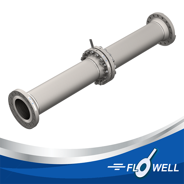
When standard components do not fit the available space, custom meter tubes can combine the primary element, taps, flanges, straight sections, and conditioning components into one controlled assembly. That reduces field variability and raises confidence in the final measurement. Dimensional accuracy, bore alignment, and consistent tap geometry also depend on precision custom machining.
Installation and Maintenance Best Practices
Even a well-chosen meter and conditioner can underperform if assembly is careless. Small errors become measurable in high-accuracy service. Good practice includes:
- Follow the manufacturer installation instructions for the primary element
- Confirm required upstream and downstream straight run before fabrication
- Verify pipe internal diameter and schedule
- Align flanges, gaskets, and meter components so nothing protrudes into the bore
- Install pressure taps in the correct orientation
- Confirm flow direction before startup
- Keep impulse lines clean, properly sloped, and leak free
- Inspect flow conditioners for fouling, corrosion, or debris
- Document installation dimensions for future troubleshooting
Maintenance should preserve the original geometry and flow path. Check plates for sharp edge condition, flatness, and bore size, and check venturi and nozzle meters for erosion or buildup. In services with solids, liquids, paraffin, or scale, routine inspection is critical because any buildup that changes the bore or conditioner passages changes the DP signal. A documented flow meter accuracy and calibration routine helps catch drift before it affects reported volumes.
Frequently Asked Questions About DP Flow Conditioning
What are flow conditioning requirements for DP flow meters?
They are the straight pipe lengths, installation practices, and conditioning devices needed to create a stable velocity profile before fluid enters the meter. Meeting them improves accuracy, repeatability, and signal stability.
Why is upstream straight run important for DP flow meters?
Upstream straight run gives disturbances time to settle before the fluid reaches the meter. Without enough pipe, swirl, turbulence, or an asymmetric profile can cause inaccurate differential pressure readings.
How much downstream straight run does a DP meter need?
It depends on the meter type, piping layout, and manufacturer guidance. Downstream lengths are usually shorter than upstream lengths, but they should still be followed to support stable pressure recovery.
When should a flow conditioner be used?
Consider one when straight pipe is limited, when upstream disturbances are severe, or when accuracy is critical. Conditioners are especially useful near elbows, valves, reducers, headers, pumps, and compact skids.
Do flow straighteners eliminate the need for straight pipe?
Not completely. Straighteners can reduce the required run in many applications, but spacing still matters. The meter, conditioner, and piping layout should be evaluated together.
Can poor flow conditioning damage a DP meter?
Poor conditioning mostly affects accuracy rather than physical integrity. Still, unstable flow, vibration, pulsation, debris, or erosion can contribute to wear and maintenance issues over time.
Are flow conditioning needs different for gas and liquid applications?
Yes. Density, compressibility, viscosity, and Reynolds number change how flow behaves. Steam, wet gas, dirty liquids, and multiphase flow may need special attention.
What is the best way to improve DP measurement stability?
Combine proper meter selection, adequate straight run, quality installation, and the right conditioning device when needed. Demanding applications often benefit from a custom-engineered meter run.
Precision Flow Measurement Support From a Tulsa Manufacturer
Stable DP measurement depends on the right equipment, the right layout, and a manufacturing partner who understands field conditions. Flowell Corporation builds custom machined components and flow measurement equipment for the oil and gas industry from Tulsa, OK, backed by three decades of experience and a skilled team focused on precision workmanship.
If your meter run has tight space, difficult upstream piping, or demanding accuracy targets, talk with a measurement specialist about the right conditioning approach for your application.