Square-Edge Orifice Plate Standards: ISO 5167, API 14.3 and Compliance Guide
Understanding square-edge orifice plate standards is essential for any operation that depends on accurate differential pressure flow measurement, from oil and gas production to petrochemical, chemical processing, and power generation. A square-edge plate looks simple, but its performance depends on precise machining, correct installation, documented inspection, and adherence to recognized standards. When the bore edge, plate thickness, pressure taps, meter tube, gaskets, or straight-run piping fall short, the measurement can become unreliable, expensive, and hard to defend during an audit or custody transfer review.
Square-Edge Orifice Plate Standards Overview
A square-edge orifice plate is a primary flow element that creates a pressure drop in a pipeline. By measuring the differential pressure across the plate, operators calculate flow rate from accepted equations and the known properties of the fluid. The “square-edge” name refers to the sharp upstream edge of the bore, which produces a predictable flow contraction, known as the vena contracta, just downstream of the plate.

The documents most often referenced for these plates are ISO 5167, ASME MFC-3M, and API MPMS Chapter 14.3, which is closely tied to AGA Report No. 3 for natural gas and hydrocarbon measurement. They are not interchangeable in every detail, but they share one goal: making differential pressure measurement repeatable, accurate, and based on proven practice. In oil and gas, the governing standard usually depends on the fluid, contract terms, regulatory expectations, and whether the measurement supports process control, allocation, reporting, or custody transfer.
Square-Edge Orifice Plate Standards Explained: ISO 5167 and API MPMS 14.3
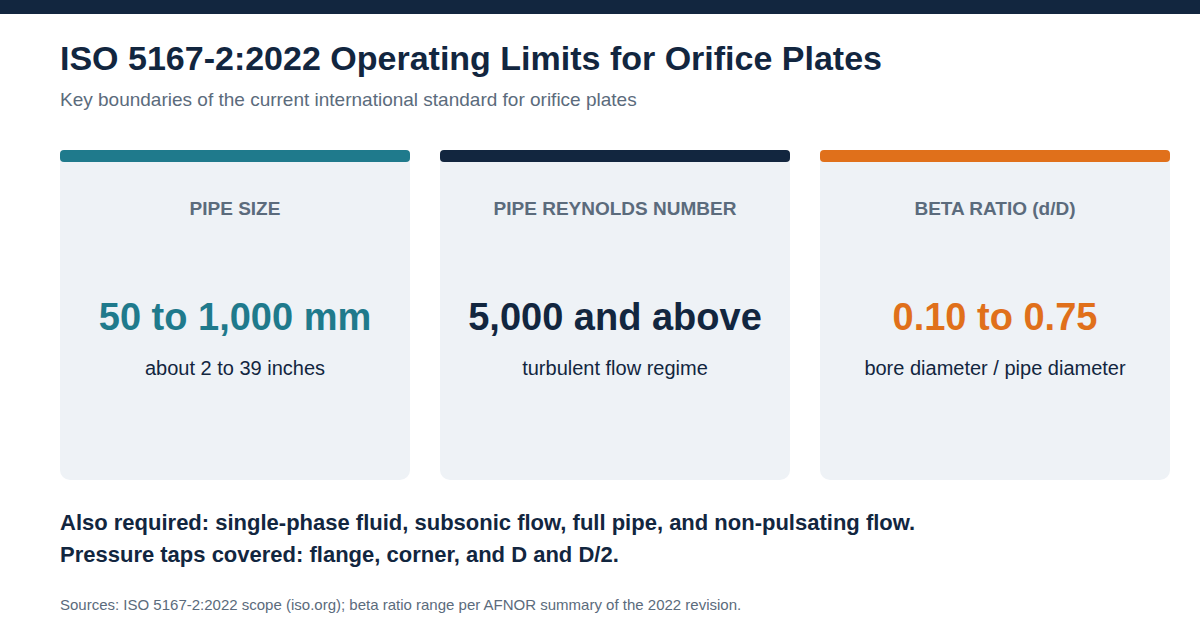
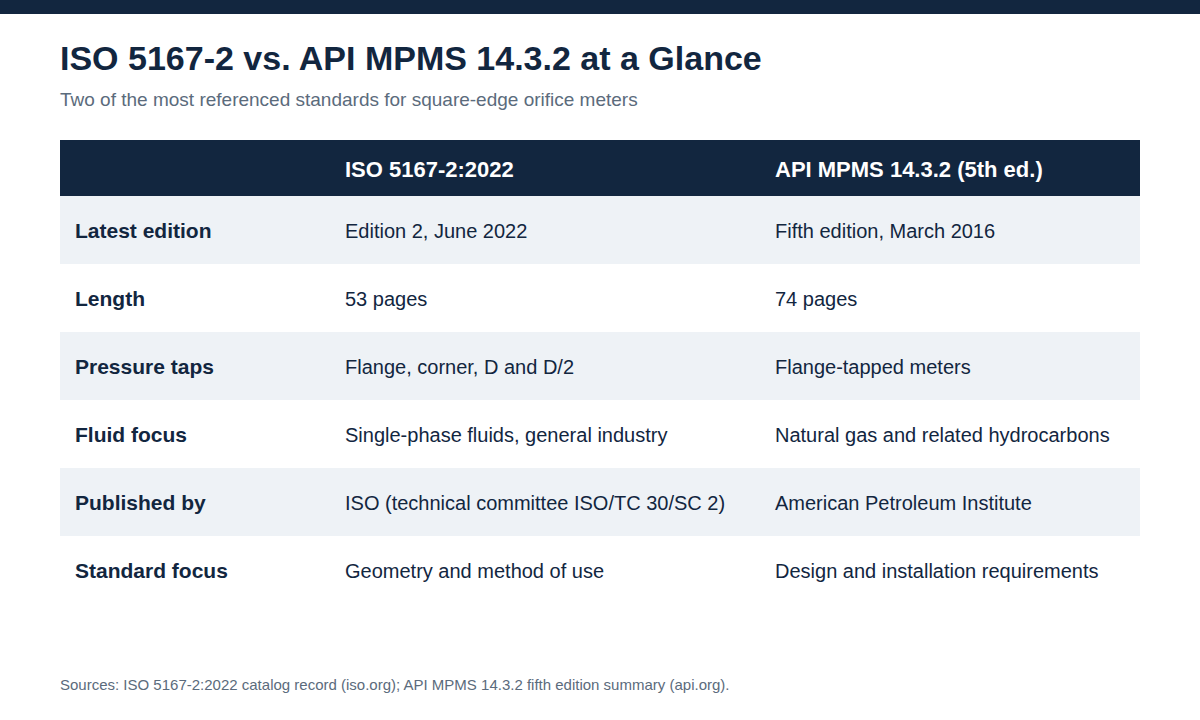
The current international reference is ISO 5167-2:2022, the second edition published in June 2022. It specifies the geometry and method of use of orifice plates installed in a conduit running full. It applies to plates used with flange, corner, or D and D/2 pressure taps, to subsonic single-phase flow, and it does not apply to pulsating flow. It also excludes pipe sizes below 50 mm or above 1,000 mm and pipe Reynolds numbers below 5,000.
In natural gas, API MPMS Chapter 14.3.2 carries the most weight. Its fifth edition, issued in March 2016, sets design and installation parameters for concentric, square-edged, flange-tapped orifice meters and cautions that measurement bias can result from inadequate flow conditioning or too little upstream pipe. ASME MFC-3M likewise covers the geometry and method of use of orifice, nozzle, and venturi devices in closed conduits running full.
In general, these standards address the following:
- Bore diameter and beta ratio limits
- Plate thickness and flatness
- Upstream edge sharpness and surface finish
- Pressure tap location and configuration
- Meter tube dimensions and roundness
- Straight pipe run and flow conditioner requirements
- Fluid and flow profile limitations
- Calculation procedures and uncertainty
A plate performs best inside the assumptions of its standard. The fluid should be clean, homogeneous, and single-phase, the pipe should run full, and the flow profile should be stable and developed. Pulsation, swirl, entrained liquids, dirty gas, damaged pipe interiors, or poorly placed fittings introduce error and reduce confidence in the data.
Manufacturing and Installation Requirements
Because the plate is the primary element, any geometry error flows directly into the calculated flow rate. Small deviations in bore diameter, edge sharpness, flatness, or finish can shift the discharge coefficient and widen measurement uncertainty. That is why many operators specify custom orifice plates built to the exact pipe size, bore, and material their application requires.
Material selection comes first. The alloy must suit the process fluid, temperature, pressure, and corrosion environment. Stainless steel and other alloys are common for their strength and long-term dimensional stability, and sour service, erosive flow, chemical exposure, and pressure cycling all deserve review in harsh oil and gas applications.
The bore must be machined accurately and centered. A concentric square-edge plate places the bore at the center of the plate, while eccentric or segmental designs serve special conditions. The conventional concentric bore remains the standard choice for most differential pressure measurement, including the universal type orifice plates used in everyday process and production service.
Installation matters as much as machining. A correctly built plate can still deliver poor results if it is installed backward, misaligned, damaged during handling, fitted with the wrong gasket, or placed too close to elbows, valves, reducers, or headers. Key checks include:
- Confirming the sharp upstream edge faces the flow
- Verifying the plate is centered in the meter tube or fitting
- Using the correct gasket and keeping it out of the flow path
- Matching pressure tap locations to the selected standard
- Maintaining upstream and downstream straight-run lengths
- Specifying a conditioner where swirl or distortion cannot be avoided
- Keeping the meter tube bore clean, round, and free of scale or weld intrusion
- Verifying markings for bore size, material, tag number, and flow direction
Pressure Taps, Straight Run, and Flow Conditioning
Common tap arrangements are flange taps, corner taps, and D and D/2 taps, and the calculation method must match the installed arrangement. Flange-tapped meters dominate natural gas measurement under API and AGA guidance. Orifice plates are also sensitive to upstream disturbances, so elbows, tees, valves, reducers, regulators, and headers all need adequate straight pipe. Where the layout cannot provide it, straightening vanes help restore a stable profile, and a purpose-built meter tube keeps the plate, taps, and straight sections in one controlled assembly.
Tolerances and Surface Finish Requirements
Tolerances exist so the plate behaves predictably under real operating conditions. The characteristics that matter most are bore diameter, plate thickness, flatness, upstream edge condition, bevel geometry, and surface finish.
The bore must be measured accurately because it sets the beta ratio, the bore diameter divided by the meter tube internal diameter. Beta influences differential pressure, permanent pressure loss, and uncertainty, and the 2022 revision of ISO 5167-2 keeps it between 0.10 and 0.75. A bore that is too large or small for the service can degrade accuracy or push the meter outside its preferred range, which is why proper orifice plate sizing belongs at the start of every project.
| Characteristic | What the standards expect | Why it matters |
|---|---|---|
| Upstream edge | Sharp and square, with no rounding, nicks, burrs, or chips | Controls flow separation and the discharge coefficient |
| Bore diameter | Accurately measured and, for concentric plates, properly centered | Sets the beta ratio and the flow calculation |
| Plate flatness | Flat faces without unacceptable warping | Keeps edge geometry consistent under pressure |
| Plate thickness | Controlled to suit bore and service | Too thick alters the opening, too thin loses rigidity |
| Downstream bevel | Provided where thickness and bore size require it | Preserves the sharp upstream geometry |
| Surface finish | Clean, smooth upstream face free of pitting and deposits | Prevents flow disturbance near the plate surface |
| Marking and traceability | Permanent marks that do not touch the sealing surface or flow path | Supports audits and correct installation |
Damage to the upstream edge changes how the fluid separates as it passes through the bore, and that shifts the discharge coefficient. Roughness, scratches, corrosion, and deposits do similar harm to the face of the plate. For operators handling allocation or custody transfer volumes, these tolerances are not cosmetic preferences. Even small errors can create significant financial exposure over time, and precision work from a shop with precision custom machining capability is what holds them in check.
Ensuring Compliance With Industry Standards
Compliance starts before machining. The purchaser or engineer should define the applicable standard, fluid service, meter tube size, tap configuration, bore calculation, material, inspection documentation, and marking requirements. Clear specifications reduce manufacturing errors and make sure the finished plate matches the design of the measurement system.
Documentation should follow each step. It commonly includes material test reports, dimensional inspection reports, bore measurement records, surface finish verification, edge inspection, and a certificate of conformance. In regulated or high-value measurement, the paperwork matters as much as the part.
Inspection also continues after delivery. Plates should be checked during installation, commissioning, maintenance, and verification work, since erosion, corrosion, edge wear, contamination, gasket damage, and handling damage can all bias the measurement over time. Pairing those checks with a documented flow meter accuracy and calibration routine catches drift before it reaches production accounting.
Inspection and Verification Practices
Trained personnel should inspect with calibrated tools and documented procedures. Typical practices include:
- Verifying tag number, bore size, material, and flow direction markings
- Measuring the bore diameter at multiple points
- Checking the upstream edge for nicks, burrs, rounding, or erosion
- Inspecting flatness, surface finish, and the downstream bevel
- Inspecting the meter tube for cleanliness, roundness, and internal damage
- Checking gasket alignment and condition
- Confirming pressure taps are clean and unobstructed
- Reviewing plate orientation before startup
Verification should include a review of operating conditions as well. A perfectly manufactured plate can still be the wrong plate if flow rate, pressure, temperature, fluid properties, or beta ratio drift outside the expected range. The most common compliance problems are:
- A bore size that no longer suits the current operating range
- A damaged upstream edge from rough handling
- Gaskets protruding into the pipe bore
- A plate installed with the bevel facing the wrong direction
- Insufficient straight pipe length
- Dirty or partially plugged pressure taps
- Meter tube corrosion or internal deposits
- Incomplete or missing inspection records
- Calculations that do not match the installed tap configuration
A proactive maintenance program reduces these risks. Set inspection intervals based on service severity, fluid cleanliness, measurement criticality, and performance history, and shorten them where solids, liquids, corrosion, or high velocities are present. Many operators also review the complete orifice plate flow meter systems they run, since holders, taps, and tubes affect compliance as much as the plate itself. For the broader measurement context, see how differential pressure flow measurement turns a pressure drop into a reliable flow rate.
Compliance also depends on choosing a capable manufacturer. A supplier should treat an orifice plate as a calibrated primary element built with careful attention to standards, documentation, and application requirements, not as a piece of metal with a hole in it.
Frequently Asked Questions About Square-Edge Orifice Plate Standards
What is a square-edge orifice plate?
A square-edge orifice plate is a thin plate with a precisely machined bore and a sharp upstream edge. Installed in a pipeline, it creates a differential pressure that is used to calculate flow rate.
Which standards apply to square-edge orifice plates?
Commonly referenced standards include ISO 5167, ASME MFC-3M, and API MPMS Chapter 14.3, also known in many natural gas applications as AGA Report No. 3. The right choice depends on the industry, fluid, meter design, and measurement purpose.
What are the limits of ISO 5167-2?
ISO 5167-2:2022 does not cover pipe sizes below 50 mm or above 1,000 mm, pipe Reynolds numbers below 5,000, or pulsating flow. It applies to single-phase, subsonic flow with flange, corner, or D and D/2 taps.
Why is the upstream edge so important?
The upstream edge controls how fluid separates as it passes through the bore. A rounded, nicked, or damaged edge changes flow behavior and degrades accuracy.
What is beta ratio?
Beta ratio is the orifice bore diameter divided by the meter tube internal diameter. It affects differential pressure, pressure loss, and measurement uncertainty.
Can an orifice plate be installed backward?
Yes. If the bevel or markings are ignored, a plate can be installed in the wrong direction, which causes significant measurement error. Always verify flow direction and orientation.
How often should orifice plates be inspected?
Frequency depends on service conditions and how critical the measurement is. Clean, stable service may need less frequent checks, while corrosive, dirty, erosive, or high-value applications should be inspected more often.
What documentation should come with a compliant orifice plate?
Documentation may include material certifications, dimensional inspection records, bore measurement reports, surface finish verification, and a certificate of conformance. Specify requirements when ordering.
Why choose a custom-machined orifice plate?
Custom machining builds the plate for the exact pipe size, bore, material, pressure class, tap arrangement, and service conditions. That supports better fit, documentation, and measurement confidence.
Standards-Compliant Orifice Plates From a Tulsa Manufacturer
When accuracy, reliability, and compliance matter, you need a partner that understands both precision machining and flow measurement. Flowell Corporation serves the oil and gas industry from Tulsa, OK, with three decades of experience and a skilled team focused on quality products and dependable service.
To discuss square-edge plates, flow measurement products, or precision machining for a demanding application, connect with a measurement specialist today.