Orifice Flange Union
Flowell manufactures orifice flange unions for industrial differential pressure flow measurement in gas, liquid, and steam service. These precision-machined assemblies are one of the most widely used primary element configurations in the field because they combine a proven measurement method, practical field serviceability, and dependable construction that holds up in demanding process environments. Teams comparing available configurations can move directly to the orifice flange union product page to request a quote or get sizing help, or continue reading for full application and selection guidance.
Selection depends on more than line size alone. Pressure class, face type, tap configuration, material, beta ratio, and the surrounding installation geometry all affect how well the assembly performs over time. For teams working through those details, sizing support is available to help narrow down the right configuration before ordering.
What is an orifice flange union?
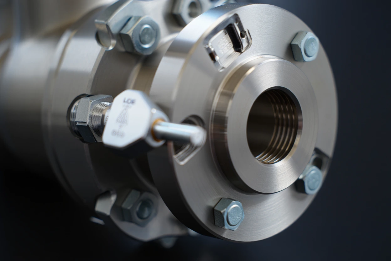
An orifice flange union is a matched flange pair with integrated pressure taps machined directly into the flange faces. The assembly is designed to hold a precision orifice plate between the two flanges so that the pressure differential created across the plate bore can be measured and converted into a flow rate. This configuration is a core component in differential pressure flow measurement and is widely used across industrial piping systems where a reliable, maintainable primary element is required.
The “union” designation refers to the paired nature of the assembly. Both flanges are machined and matched together so the pressure taps align correctly, the plate seats consistently, and the sealing faces meet the requirements of the installation. Getting those details right during manufacturing is what separates assemblies that hold their calibration from ones that drift or require frequent attention in the field. For a focused breakdown of what distinguishes this component, what is an orifice flange covers the key design and function points in more detail.
Orifice flange unions are distinct from standard pipe flanges. The integrated taps and precision-machined sealing geometry are purpose-built for measurement, not just mechanical connection.
How an orifice flange union measures flow
The measurement principle is based on the relationship between fluid velocity and pressure. When process fluid passes through the restricted bore of the orifice plate, velocity increases and static pressure drops. The two pressure taps built into the flange union capture that differential, one upstream and one downstream of the plate. That differential pressure signal is routed to a transmitter where it is converted into a calculated flow rate using established DP methodologies.
Measurement accuracy across the full operating range depends on plate flatness, bore concentricity, edge sharpness, and consistent plate seating with every installation. It also depends on the surrounding piping. Upstream disturbances from elbows, valves, and reducers can distort the flow profile before it reaches the plate, which is why straight-run requirements and flow conditioning hardware deserve attention during the design phase. Teams working through complete meter run design can review orifice plate flow meter systems for a broader look at how the full assembly comes together.
Orifice flange union pressure tap configurations
Tap placement is one of the more consequential decisions in specifying a flange union. The three most common configurations each relate to a different standard and produce slightly different results in practice.
| Tap Type | Location | Common Use Case |
|---|---|---|
| Flange taps | 1 inch upstream and 1 inch downstream from plate face | Most widely used configuration in North American practice |
| Corner taps | Immediately adjacent to the plate on both sides | Common in European standards and smaller line sizes |
| Pipe taps | 2.5D upstream and 8D downstream from plate | Used in older installations and some specific AGA applications |
The tap style should match the calculation methodology being used on the project. If a specific standard is referenced in the project specification, include it when submitting details through contact us so the right configuration can be confirmed before manufacturing.
Orifice flange union face types and pressure class options
Face type and pressure class are the two specification decisions that most directly affect sealing performance and compatibility with the surrounding piping system. Both need to match the mating flanges and the demands of the service conditions.
Raised face (RF)
The most commonly specified face type in general industrial service. RF flanges use a raised seating surface that concentrates bolt load on the gasket, making them practical across a broad range of pressure classes and process conditions. They are widely compatible with standard gasket materials and well understood by most piping crews.
Ring-type joint (RTJ)
RTJ faces are more commonly specified at higher pressure classes and in services where a metal-to-metal seal is preferred. The ring groove machined into the flange face accepts a soft metal ring gasket that deforms into the groove under bolt load. This approach is often required in high-pressure oil and gas service and sour environments. Related hardware such as RTJ plate holders may also be part of the assembly in these applications.
Pressure class reference
| Pressure Class | Typical Service Context | Notes |
|---|---|---|
| CL150 | Low-pressure utility and process service | Common starting point for general industrial installations |
| CL300 | Moderate-pressure service | Suitable for a wide range of gas and liquid applications |
| CL600 | Higher pressure process lines | Often seen in refining and chemical service |
| CL900 / CL1500 | High-pressure and critical service | RTJ faces more common at these classes |
Confirming pressure class for your installation
Pressure class selection should always be confirmed against ASME B16.5 or the applicable piping specification for the project. Do not upsize or downsize based on cost alone. The flange class needs to match the design pressure, temperature, and material combination for the service.
Where orifice flange unions are used
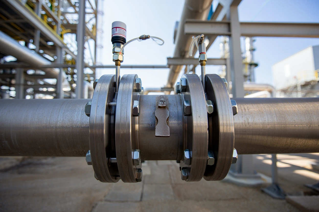
Orifice flange unions are found in virtually every industrial sector where fluid flow needs to be measured. Their combination of precision, familiarity, and serviceability makes them a natural fit wherever differential pressure measurement is specified as the standard approach. A full breakdown of where these assemblies see the most use is covered in common applications of orifice flanges.
Oil and gas
Used across upstream, midstream, and downstream operations including fuel gas, gathering systems, produced water lines, flare and vent monitoring, and custody transfer meter runs.
Chemical and petrochemical
Applied in process control loops, utility services, and monitoring applications where accurate flow data supports operational decisions and safety systems.
Power generation
Installed in steam, condensate, and boiler feedwater systems where precise measurement contributes to efficiency, safety monitoring, and regulatory compliance.
Water and wastewater
Used in process monitoring, chemical dosing, and distribution systems where rugged construction and reliable repeatability are important over long service intervals.
Industrial facilities
Found in compressed air, nitrogen, and process liquid lines across manufacturing plants, refineries, and industrial facilities where flow monitoring supports operations and compliance.
Midstream and pipeline
Specified for allocation measurement, pipeline monitoring, and custody transfer applications where the measurement needs to hold up to regulatory scrutiny and third-party verification.
Benefits of orifice flange unions in flow measurement
There are reasons this assembly has remained a dominant choice in industrial flow measurement for decades. The combination of measurement reliability, broad application range, and practical serviceability is difficult to match with more complex technologies in many service environments. A deeper review of the advantages is available through benefits of using orifice flanges for flow measurement.
Choosing the right orifice flange union for your application
The decision-making process for selecting an orifice flange union works best when it starts with the service conditions rather than a catalog preference. The following factors typically drive the most important specification decisions.
- Line size and internal diameter affect bore sizing and the beta ratio that will produce a usable differential at the expected flow range
- Pressure class must match the design pressure, temperature, and material combination per ASME B16.5 or the applicable project standard
- Face type should match the mating flanges already in the piping system and the sealing requirements of the service
- Tap configuration needs to align with the calculation methodology and any referenced standard for the project
- Material depends on media, temperature, corrosion potential, and whether documentation such as material test reports is required
- Beta ratio is determined by line size, operating flow range, allowable pressure drop, and instrument span
- Surrounding installation geometry including available straight run, upstream fittings, and potential flow disturbances all influence whether the assembly will deliver consistent readings in service
Teams working through beta ratio and bore sizing can use sizing support to get a recommendation aligned to the actual process conditions.
Orifice flange union materials and construction
Material selection for an orifice flange union should be driven by the process fluid, operating temperature, corrosion potential, pressure class, and any project documentation requirements. The machined features that matter most for measurement, specifically the sealing faces, tap bores, and plate seating surfaces, need to be held to tight tolerances regardless of the base material selected. Flowell machines and inspects these features to help maintain consistent differentials and reduce drift over time.
| Material | Best Fit | Notes |
|---|---|---|
| Carbon steel | General-purpose service, cost-effective applications | Suitable where corrosion resistance is not the primary concern |
| 304/316 stainless steel | Corrosive media, aggressive environments | Better resistance to a broad range of process chemistries |
| Special alloys | High temperature, sour service, unique chemistries | Available on request through custom machine work |
Material test reports are available on request for projects with documentation requirements. If your project involves non-standard dimensions or alloy specifications, Flowell can assist through custom machine work.
Installation factors that affect orifice flange union performance
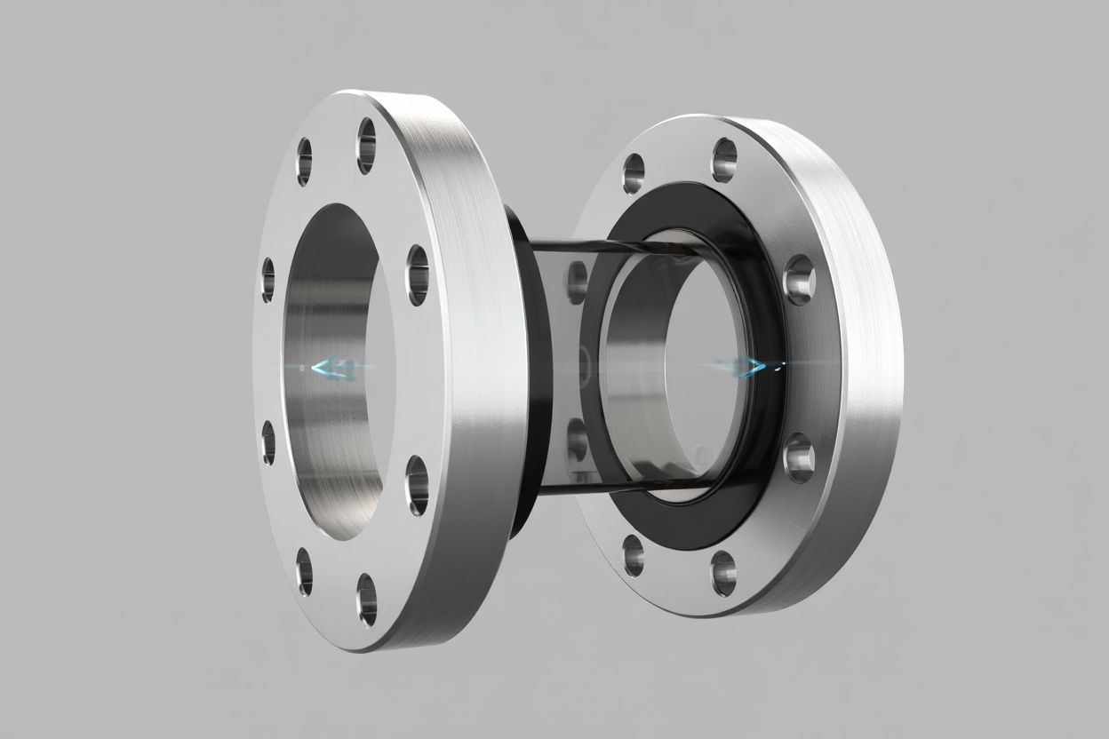
Even a correctly specified and well-machined assembly can underperform if the surrounding installation introduces flow disturbances that the plate cannot compensate for. Upstream geometry, straight-run availability, and supporting hardware are all part of the measurement system and deserve the same attention as the flange union itself.
Straight-run requirements
The orifice plate needs a stable, fully developed flow profile to produce a consistent differential. Elbows, tees, reducers, control valves, and other fittings upstream of the measurement point introduce swirl and turbulence that can shift the reading. Standard practice calls for a minimum number of pipe diameters of straight run upstream and downstream of the plate, with the exact requirement depending on the beta ratio and the type of upstream disturbance.
When the available straight run is constrained, meter tubes provide a manufactured straight-run section with known internal geometry, and straightening vanes can reduce swirl in cases where the physical layout cannot provide the full straight-run length.
Common causes of measurement drift
- Insufficient upstream straight run allowing flow profile distortion
- Swirl from elbows or valves close to the measurement point
- Plate misalignment or inconsistent seating during installation
- Debris accumulation on the plate edge over time
- Pressure tap blockage or partial obstruction
- Incorrect beta ratio for the actual operating flow range
- Condensate in the instrument impulse lines for gas service
Supporting instrumentation
Steam and certain gas applications may require condensate management hardware. Condensate chambers help maintain a stable liquid seal in the impulse lines so the transmitter sees a consistent reference. In applications where venting or draining capability is needed at the flange, bleed rings can be incorporated into the assembly.
Comparing orifice flange unions with other DP primary elements
Orifice-based measurement is not the only approach to differential pressure flow measurement, and for some services another primary element makes better sense. The table below helps frame the comparison.
| Primary Element | Permanent Pressure Loss | Typical Fit | Flowell Link |
|---|---|---|---|
| Orifice flange union | Moderate, depends on beta ratio | Broad industrial service, well-established standards | View product |
| Venturi tube | Lower permanent loss | When pressure recovery and lower loss are a priority | Venturi tubes |
| Flow nozzle | Moderate to lower | High-velocity or erosive service where plate edge wear is a concern | Flow nozzles |
For a broader review of how these measurement approaches compare and when each makes the most sense, differential pressure flow measurement covers the full DP measurement landscape, and flow measurement systems provides context for how the full assembly comes together across different service types.
Broader flow meter comparison
Teams evaluating DP measurement against non-DP alternatives may also find value in reviewing ultrasonic vs differential pressure flow meters and the different types of flow meters for a full landscape view before committing to a technology.
Related flow measurement components
An orifice flange union is one part of a larger measurement system. The hardware that surrounds it directly affects how well the full assembly performs. Below are the components most commonly specified alongside a flange union for a complete and dependable meter run.
Paddle-type orifice plates
The primary element that seats between the flange union faces. Bore sizing, edge condition, and plate flatness directly affect the quality of the differential that drives the flow calculation.
Meter tubes
Provide the manufactured straight-run geometry needed upstream and downstream of the flange union to deliver a stable, undisturbed flow profile to the primary element.
Straightening vanes
Installed upstream to reduce swirl and flow distortion when the available piping layout cannot provide the full straight-run length required by the beta ratio.
RTJ plate holders
An alternative plate-holding arrangement for higher pressure class applications where ring-type joint sealing is specified.
Bleed rings
Installed at the flange connection where venting or draining capability is needed at the measurement point during maintenance or commissioning.
Condensate chambers
Used in steam and certain gas applications to maintain a stable liquid seal in the impulse lines and protect transmitter accuracy over time.
For the full range of available components, visit flow measurement products or return to the Flowell homepage.
Standards and methodology for orifice flange unions
DP flow measurement through orifice plates is governed by well-established standards that define calculation methodology, installation requirements, and acceptable tolerances. The most widely referenced include ISO 5167 for differential pressure devices in closed conduits and American Gas Association (AGA) methodologies for natural gas measurement applications. ASME B16.5 governs flange dimensions and pressure-temperature ratings for the flange union itself.
If your project references a specific standard or methodology, include that detail when submitting your application data so the configuration can be aligned correctly before manufacturing. Tap style, face type, bore sizing, and material documentation requirements can all vary depending on which standard applies to the project.
Orifice flange union FAQs
What is the difference between an orifice flange union and a standard pipe flange?
A standard pipe flange is a mechanical connection component with no measurement function. An orifice flange union is a matched pair with precision-machined pressure taps, a controlled seating surface for the orifice plate, and dimensional tolerances that support repeatable differential pressure flow measurement. The two are not interchangeable in a metering application.
What orifice plate style is used with a flange union?
Paddle-type orifice plates are the most common pairing with a flange union. The plate sits between the two flange faces and is clamped in place by the bolting. Paddle-type orifice plates are available directly from Flowell and can be sized to match the flange union configuration.
How do I determine the correct beta ratio for my orifice flange union?
Beta ratio (d/D) depends on pipe internal diameter, the operating flow range, allowable permanent pressure loss, and the instrument differential range. The goal is to choose a bore that keeps the differential within the transmitter range across the full expected flow range without exceeding the allowable pressure drop. Submit your process data through sizing support and Flowell will recommend a bore size aligned to your conditions and methodology.
Can the orifice plate be replaced without removing the flange union from the line?
Yes. One of the practical advantages of a union-style assembly is that the plate can be accessed for inspection, replacement, or re-ranging by unbolting the flange pair without cutting out the assembly. This simplifies maintenance during turnarounds and reduces the time the line needs to be out of service.
What is the difference between RF and RTJ face types on an orifice flange union?
RF (Raised Face) uses a raised seating surface with a soft gasket and is widely used in general industrial service across most pressure classes. RTJ (Ring-Type Joint) uses a machined ring groove and a metal ring gasket for a metal-to-metal seal that is more common at higher pressure classes and in sour or high-temperature service environments. The right choice depends on the mating flange type already in the piping system and the sealing requirements of the service.
What information does Flowell need to quote an orifice flange union?
The most useful details to include are line size and schedule, pressure class, face type (RF or RTJ), tap configuration, material, media and process conditions (temperature, pressure, density/viscosity), expected flow range, allowable pressure drop, orifice plate details if known, and any applicable standard or methodology. Send those details through contact us or sizing support for a fast response.
Talk with Flowell about orifice flange unions
Whether you are designing a new meter run, replacing an aging assembly, or evaluating options for a difficult service, Flowell can help review the operating conditions and narrow down the right configuration. Send your process details through contact us, start with sizing support, or move directly to the orifice flange union product page to request a quote. You can also return to the Flowell homepage to explore more flow measurement products and resources.