How Viscosity and Density Affect Flow Measurement Accuracy
Viscosity and density in flow measurement decide whether a meter that was accurate on the day it was calibrated stays accurate on the day the process changes. A cold morning on a crude gathering line, a new blend arriving at a terminal, or a swing in gas composition at a metering skid can all move fluid properties away from design values. The meter rarely fails outright. It drifts, and the drift hides inside daily totals until a custody transfer reconciliation or an audit exposes it.
This guide explains the physics in practical terms: how density enters the flow equation, how viscosity sets the flow regime through the Reynolds number, what the ISO 5167 standards require of orifice plates, nozzles, and Venturi tubes, and what you can do at the sizing, selection, and verification stages to keep errors small. Flowell Corporation machines these primary elements for oil, gas, and process customers, so the focus is differential pressure metering, with a comparison to other meter types.
What Density and Viscosity Actually Do in a Flowing Pipe
Density: The Variable Behind Mass Flow
Density is mass per unit volume. In a differential pressure meter it sits directly inside the flow equation: mass flow is proportional to the square root of differential pressure multiplied by flowing density, as written in ISO 5167-1. Volumetric flow is mass flow divided by density, so it varies with the square root of differential pressure divided by density. The familiar shortcut that flow follows only the square root of differential pressure is true only while density stays constant.
In liquids, density moves slowly with temperature and composition. In gases it moves quickly with pressure, temperature, and composition, which is why gas metering relies on live pressure and temperature transmitters and compressibility calculations rather than a fixed density entry.
Viscosity: The Variable Behind the Flow Regime
Viscosity is a fluid’s internal resistance to shear. It controls how velocity is distributed across the pipe bore. The U.S. Department of Energy treats flow regime as a function of the Reynolds number in its Fundamentals Handbook on thermodynamics, heat transfer, and fluid flow, and for practical purposes flow below a Reynolds number of 2,000 is laminar. In laminar flow, fluid layers slide past one another and the velocity profile is parabolic, with the centerline velocity at twice the cross-sectional average. Turbulent flow mixes the fluid, flattens the profile, and behaves far more predictably for measurement.
Why Temperature Changes Density and Viscosity Together
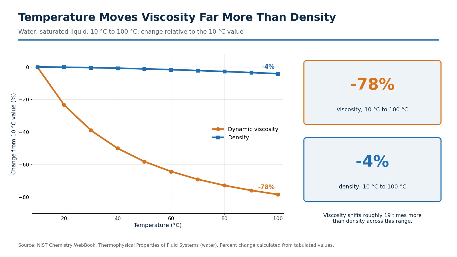
For liquids, rising temperature lowers both density and viscosity, but not by the same amount. Water makes the point clearly. Using values tabulated in the NIST Chemistry WebBook, water between 10 °C and 100 °C loses about 78 percent of its viscosity but only about 4 percent of its density. Hydrocarbons move in the same direction, with magnitudes that depend on composition. Gases behave differently: at constant pressure their density falls as temperature rises, while their viscosity creeps upward.
How Viscosity and Density in Flow Measurement Shape Accuracy
The Reynolds Number Ties Both Properties Together
The pipe Reynolds number equals density times velocity times pipe diameter, divided by dynamic viscosity. Because density and viscosity both appear in it, any change in either one moves the operating point. There is a useful simplification, though. For a known mass flow rate, the Reynolds number reduces to four times the mass flow divided by pi times pipe diameter times dynamic viscosity. Density cancels out. In practice, the flow regime of a line carrying a fixed mass flow is a viscosity story, even though density is the property that feeds the flow equation.
The discharge coefficient of a differential pressure device depends on this Reynolds number. For orifice plates, ISO 5167-2:2022 sets the geometry and limits of use for plates with flange, corner, or D and D/2 tappings, and its coefficient equation is valid only inside those limits. Outside them, the published coefficient and its stated uncertainty no longer apply.
How Viscosity and Density in Flow Measurement Create Drift
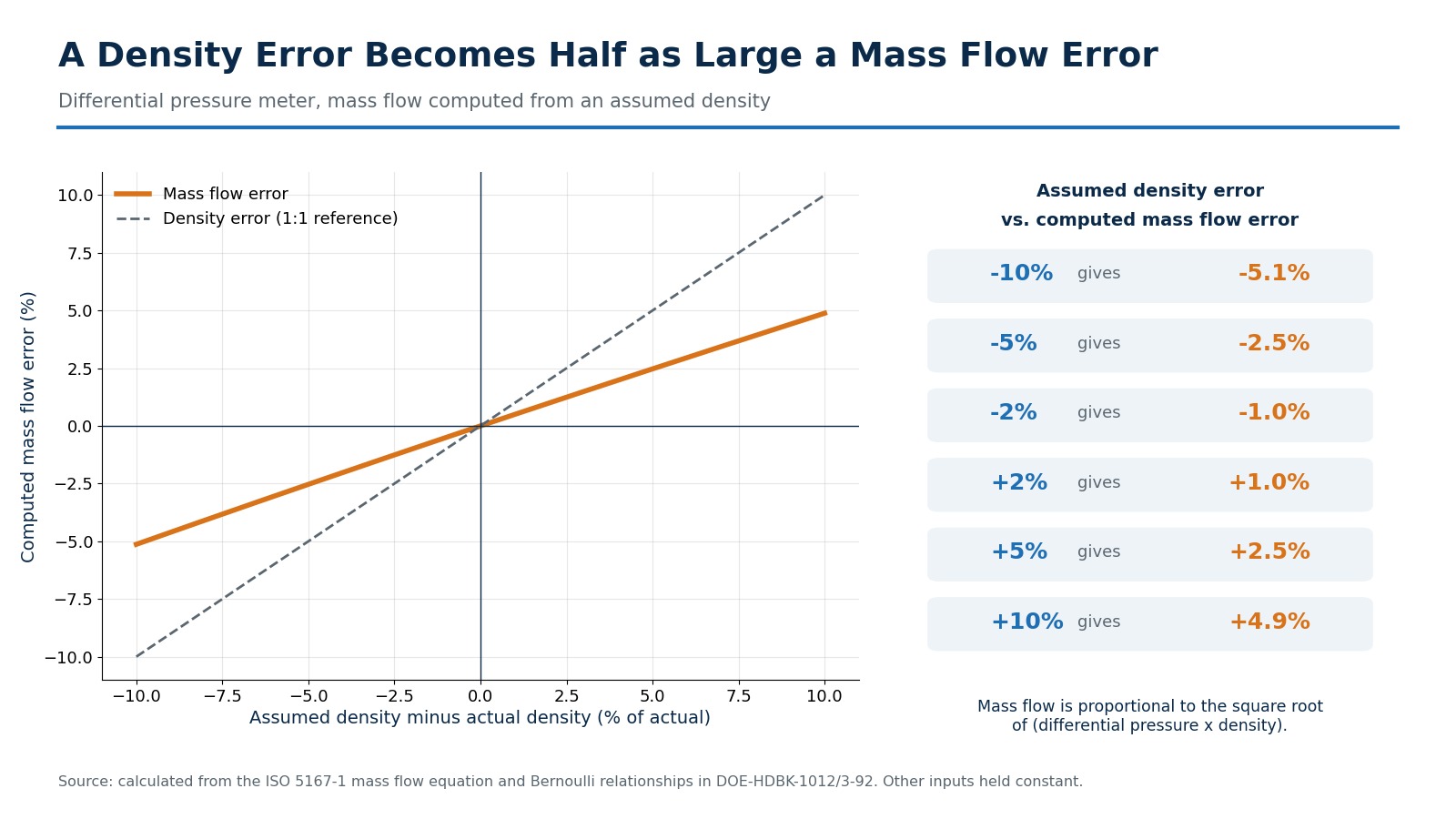
Fluid properties reach the measurement through two separate paths, and they can compound. The first is the density path. A flow computer holding a fixed density entry will compute mass flow from the wrong number whenever the real density moves. If the assumed density is higher than the true value, computed mass flow reads high. If it is lower, mass flow reads low. Because of the square root relationship, the error arrives at about half the size of the density error.
The second is the viscosity path. When viscosity rises, the Reynolds number falls, the discharge coefficient moves away from the value assumed at calibration or in the standard, and the velocity profile becomes less flat. Straight-run requirements and flow conditioner performance both assume a fully developed turbulent profile, so a regime shift undermines them too. The paths compound on a cold line, where viscosity and density rise together and a flow computer may still be running summer values.
| Flow Regime | Reynolds Number | Velocity Profile | Measurement Implication |
|---|---|---|---|
| Laminar | Below 2,000 | Parabolic, centerline velocity twice the average | Outside the limits of use of all three standard differential pressure elements |
| Transitional | 2,000 to 4,000 | Unstable, shifting between laminar and turbulent | Unpredictable coefficients and noisy differential pressure |
| Turbulent | Above 4,000 | Flat, fully mixed | Standard coefficients apply once the element’s own Reynolds limit is also met |
Reynolds Number Limits for Differential Pressure Primary Elements
What the ISO 5167 Standards Require
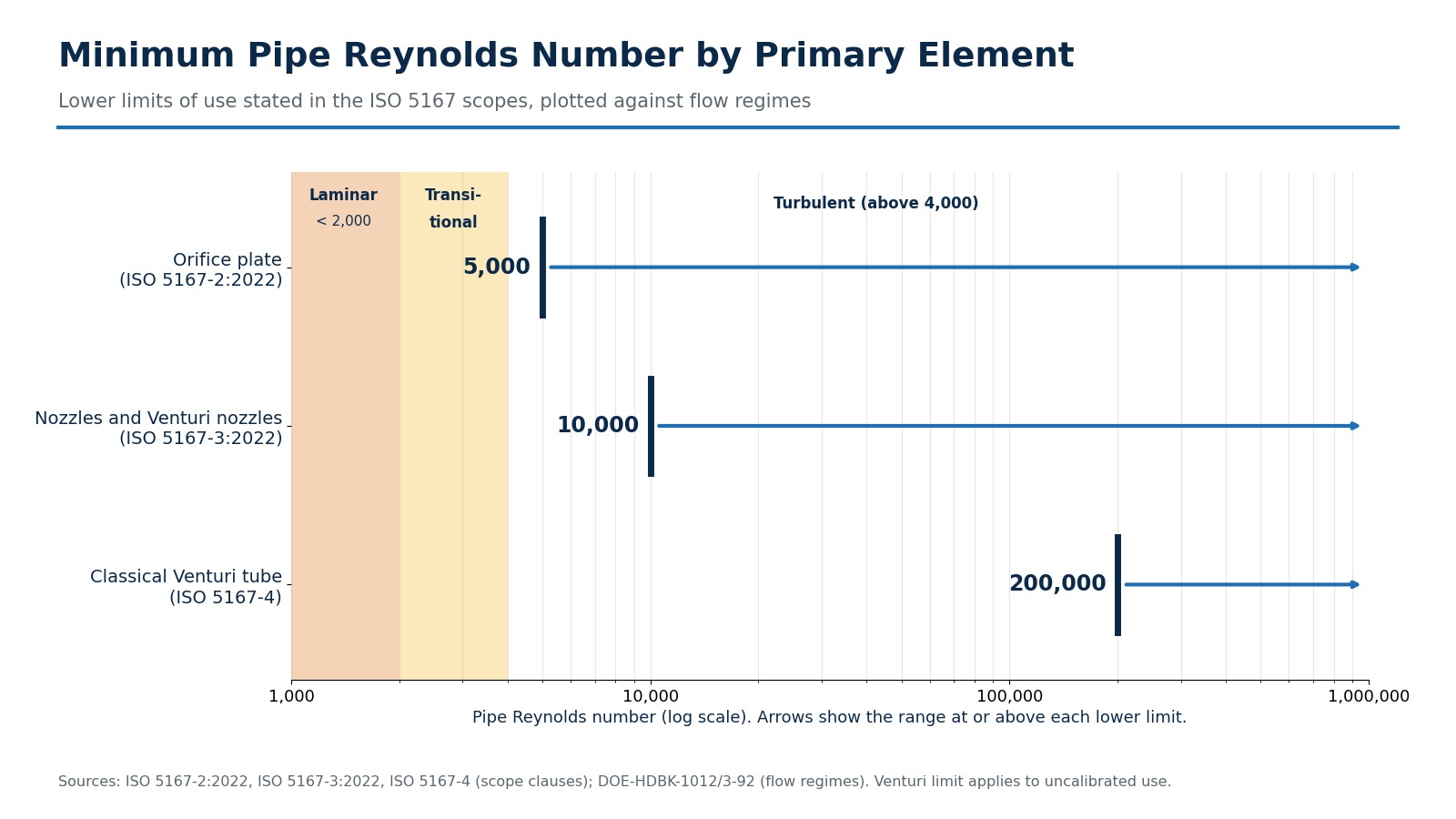
Each element in the ISO 5167 series carries its own lower Reynolds limit. Orifice plates are not covered below a pipe Reynolds number of 5,000. Nozzles and Venturi nozzles are not covered below 10,000 under ISO 5167-3:2022. Classical Venturi tubes used uncalibrated under ISO 5167-4 are not covered below 200,000, although the standard also allows a Venturi tube to be used across its calibrated range instead. These limits are the reason element selection cannot be separated from fluid viscosity.
Worked Example: A Cold Start on a 4-Inch Liquid Line
Consider a 4-inch schedule 40 line with a 102.3 mm inside diameter, a liquid density of 850 kg/m³, and a velocity of 1.5 m/s. The product of density, velocity, and diameter is about 130.4, so the Reynolds number is 130.4 divided by the dynamic viscosity in pascal-seconds. The table shows how the same line moves through the limits as the fluid thickens.
| Dynamic Viscosity | Reynolds Number | Orifice Limit (5,000) | Nozzle Limit (10,000) | Venturi, Uncalibrated (200,000) |
|---|---|---|---|---|
| 2 cP | 65,200 | Within | Within | Below limit |
| 20 cP | 6,520 | Within | Below limit | Below limit |
| 100 cP | 1,304 | Below limit | Below limit | Below limit |
| 500 cP | 261 | Below limit | Below limit | Below limit |
At this velocity the orifice limit is crossed near 26 cP, and the nozzle limit near 13 cP. The uncalibrated Venturi limit would require a viscosity under about 0.65 cP. The example is illustrative, but the lesson is general: a primary element that is correct at summer viscosity can sit outside its standard at winter viscosity. Where the coldest, lowest-flow condition falls below a limit, the answer is calibration across the working range, a different element, or a different meter technology.

How Different Meter Types Respond to Property Changes
No meter technology ignores fluid properties. They differ in which property matters and how the error reaches the reading.
| Meter Type | Density Sensitivity | Viscosity Sensitivity |
|---|---|---|
| Differential pressure (orifice, nozzle, Venturi) | Direct, since density is in the flow equation | Indirect, through Reynolds number and discharge coefficient |
| Turbine | Low for volumetric output | High at low flow rates, where bearing friction dominates |
| Positive displacement | Low for volumetric output | Internal leakage past clearances changes with viscosity |
| Ultrasonic transit time | Not needed for velocity | Velocity profile correction depends on Reynolds number |
| Coriolis | Measures mass and density directly | Low direct effect, but pressure drop rises with viscosity |
| Variable area (float type) | High, calibrated for a specific fluid | High, needs explicit correction |
Differential pressure devices remain the workhorse of oil and gas because they have no moving parts, are defined by published standards, and can be verified by dimensional inspection. Their sensitivity to density is manageable with live compensation, and their sensitivity to viscosity is manageable with proper sizing. The differential pressure metering principles behind these devices are what make that verification possible.
Practical Ways to Keep Measurement Accurate When Fluid Properties Change
Size the Primary Element for the Full Property Range
Sizing at nominal conditions is not enough. Collect the minimum and maximum flowing temperature, the density and viscosity at each extreme, and the minimum, normal, and maximum flow. Then check the Reynolds number at the lowest flow and the coldest temperature, because that is where it is smallest. Flowell offers sizing support for exactly this exercise, matching beta ratio and differential pressure span to the real process envelope instead of a single design point.
Liquid Service: Check the Cold, Low-Flow Corner
The lowest Reynolds number occurs at the coldest temperature and the lowest flow. If that point drops below the element’s limit, compare options: precision Venturi primary elements calibrated across the working range, a plate element sized for the viscosity, or another meter technology. Complete orifice meter assemblies can be specified once the Reynolds check passes.
Gas Service: Track Pressure, Temperature, and Composition
Natural gas has very low viscosity, so Reynolds numbers are typically high and viscosity is a minor concern. Density is the dominant property, and it responds to pressure, temperature, and composition together. Live transmitters feeding the flow computer, plus compressibility calculations, keep the density term honest.
Steam Service: Keep the Liquid Legs Equal
In steam lines, condensate pots for steam service keep the impulse lines filled with liquid at equal levels. That prevents the density of the sensing legs from distorting the differential pressure signal.
Match the Element to the Application
Square-edge plate elements suit clean liquids and gases when the Reynolds check passes and are easy to inspect and replace. Flow nozzle elements for higher velocities are often chosen where velocity is high, such as steam. Venturi tubes recover more pressure, which matters when permanent pressure loss is costly, and above their Reynolds limit their coefficient behavior is consistent across a wide flow range. Venturi meter installations are therefore common on larger lines where energy loss adds up.
Compensate in the Flow Computer, Then Verify Physically
A flow computer can correct density from live pressure and temperature and can iterate a Reynolds-dependent discharge coefficient. It cannot correct a distorted velocity profile. Swirl and asymmetry from upstream fittings need physical fixes: adequate straight length in precision-bored meter runs and swirl-removing vane assemblies where space is limited.
The primary element itself needs verification as well. Bore diameter, edge condition, and beta ratio determine the coefficient the flow computer assumes, and a worn or out-of-tolerance element introduces a bias that no compensation algorithm can see. A program of calibration and accuracy verification paired with dimensional inspection catches what software cannot. Flowell supports this with custom CNC machining capabilities for replacement and made-to-order elements.
Talk With Flowell About Your Process Fluid
Bring the fluid, the temperature range, the line size, and the flow range, and the engineering team can check Reynolds limits, density handling, and element selection together. Contact the Flowell engineering team to talk through a specific service, or use the sizing request to send your process data directly.
Frequently Asked Questions About Fluid Properties and Flow Measurement
Does viscosity affect orifice plate accuracy?
Yes, indirectly. Viscosity sets the pipe Reynolds number, and the orifice discharge coefficient depends on that Reynolds number. ISO 5167-2:2022 does not cover orifice plates where the pipe Reynolds number is below 5,000, so a fluid that thickens enough to cross that limit pushes the meter outside the standard’s tables and uncertainty claims.
How does density affect differential pressure flow measurement?
Density appears directly in the mass flow equation, which is proportional to the square root of differential pressure multiplied by flowing density. If the flow computer assumes a density higher than the true value, computed mass flow reads high, and if it assumes a lower value, mass flow reads low. A density error shows up at roughly half its size in mass flow.
What happens to flow measurement when the fluid gets colder?
For liquids, viscosity rises sharply and density rises slightly as temperature falls. Higher viscosity lowers the Reynolds number, which can move the flow toward the transitional or laminar range and shift the discharge coefficient. A flow computer still using warm-weather density values will also carry a density error.
Can software compensation fix viscosity and density errors?
Software handles the calculable part well. A flow computer can correct density from live pressure and temperature inputs and recalculate Reynolds-dependent coefficients. It cannot correct a distorted velocity profile caused by swirl or short straight run, which needs physical solutions such as adequate meter tube length and flow conditioning.
Which differential pressure element works best for viscous liquids?
No single element wins in every case. Orifice plates have a lower Reynolds limit of 5,000 in ISO 5167-2:2022, nozzles have 10,000, and classical Venturi tubes used uncalibrated start at 200,000. For viscous services, the practical answer is to calculate the Reynolds number at the coldest, lowest-flow condition and, where it falls below a standard’s limit, calibrate the element across its working range.
Does gas viscosity matter in flow measurement?
It matters less than in liquid service. Natural gas has a very low viscosity, so pipe Reynolds numbers are usually high and well inside the limits. In gas service, density is the dominant property, and it moves with pressure, temperature, and composition, which is why live pressure and temperature measurement is standard practice.
What fluid data should I provide for primary element sizing?
Provide the fluid name or composition, minimum and maximum flowing temperature, operating pressure, density or specific gravity across that range, viscosity at the coldest and warmest conditions, line size and schedule, and the minimum, normal, and maximum flow rates. Sizing against the full range is what prevents a design that only works at nominal conditions.
How do I know if my current meter is drifting because of fluid properties?
Compare the density and viscosity values programmed into the flow computer against current laboratory or live-measured values, and check whether the Reynolds number at your coldest, lowest-flow operating point still sits within the element’s limits. A calibration and accuracy verification program catches the remainder, including dimensional changes at the primary element.